| 4.9.6 | Building the switchboard | previous |
The switchboard can be built on a piece of 5 or 6 mm plywood of about 200 by 300 mm. There is no need to use water resistant plywood since the switchboard has to be protected against water anyway. The panel indicator, switches, lamps and fuse holder stick through it to the front side while their connections are at the back side. The regulator, current shunt, voltage measuring circuit, connection block and cable clamp block are fitted completely at the back. Since the dimensions of these components can differ widely, no drawing for the lay-out is made. Fit the components as seems best, trying to maintain a logical order and allowing space for little headings like:
Fit the battery switch and the field current switches in the same way, e.g. with the switch being `off' when the handle points upwards.
|
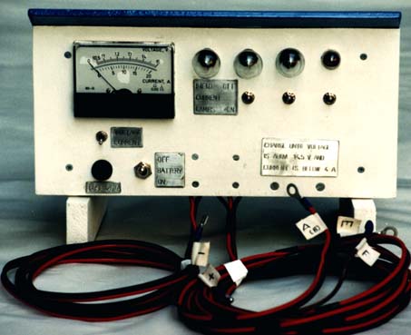
Fig. 4.29: A complete switchboard. |
On either side of the switchboard, pieces of wood are fitted onto which a plywood top cover and back cover can be fitted. By having the switchboard itself, the back cover and the top cover extend a little beyond these pieces of wood, slots are formed on either side. With these slots, the switchboard fits on two poles (with the correct thickness and distance between them) that are placed permanently on the site of the charger. Then to prevent unauthorised use of the charger, the switchboard itself can easily be lifted from the poles and taken home by the operator.
Most electric components on the switchboard can not stand being wet. Especially the indicator itself and the indicator range switch are sensitive to this. Therefor the switchboard as a whole must be well protected against rain. This can be done by covering the whole switchboard with the bottom part of a plastic jerrycan that is cut in half. Only for checking, this half jerrycan can be taken off. To prevent the switchboard from getting too hot in the sun, a white plastic jerrycan would be best. Alternatively, a layer of white plastic foil can be sticked onto it using electrical tape (paint will probably not hold). If the top cover extends a few cm over the front of the switchboard, it will protect the front during checking. The panel indicator can be protected further by sticking electrical tape over the seam between the removable, transparant front and the casing, and over the zero adjustment screw.
The different components have to be connected according to the circuit diagram of fig. 4.25. To make the connections, the proper type of wires must be chosen. For all wires, choose stranded cable because it will not break easily when bent many times. The cheapest cable usually is twin-cable, with two leads connected to form a flat cable without a jacket around the leads. This can be used in the home system, where mostly 2 leads (`+' and `-') are needed. If single wire is needed, the cable can easily be split in two.
The thickness of the wires depend on the current they have to conduct:
Having the electronic parts of the voltage measuring circuit hanging loose in the air is asking for trouble. They could be soldered on a small piece of printed circuit board, which in turn is fitted somewhere firmly. Hobby electronics shops have pre-drilled PCB board with all strips parallel in one direction, which is very suitable. But any other solution which makes that they can not break loose, create a short circuit or suffer from leakage currents, will do.
Soldering thick wires can be difficult with a small soldering iron that is meant for electronics. The thick wire conducts away heat so fast that the joint never reaches the melting point of the solder. But if the wire that conducts away the heat is isolated with layers of paper or cloth, it eventually warms up enough to be soldered.
It is adviseable to fit a connector block between the internal wires of the switchboard and the cables to the outside (to the alternator and the battery). This makes that during building and calibrating the switchboard, there are no inconveniently long and thick cables connected to it. It also makes that these cables (the most likely part to be damaged) can be changed in the field without soldering if necessary. If soldering is not a problem, it is adviseable to solder the strands together at the ends of the wires that go into the connector block. This makes it easier to fit all strands in the connector block and it provides better contact. To avoid mistakes and to make testing, measuring and troubleshooting easier, write the codes of wires (`A', `E', `F', `Batt.+' and `Batt.-') below the corresponding units of the connection block at the back of the front plate.
The cables to the outside should be fixed properly on the switchboard by a cable clamping block, which consists of two pieces of wood with the cables clamped in between. Then the plastic isolation jacket around the copper strands will prevent them from bending sharply at one point. Without such a clamping block, the strands will bend sharply where they leave the connector block and where the isolation jacket is removed. Then eventually they will break off there.
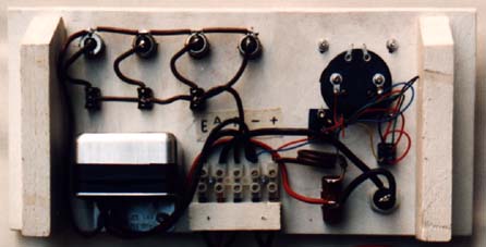 |
Fig. 4.30: The back side of the switchboard front panel, with all components and wiring fitted. |
To make sure that users will always connect their battery with the right polarity to their home system, there should be connectors between the battery and home system that fit only in the right way. Then the battery cable of the switchboard should have the same type of connector as the home system, so that it can easily be connected to the battery being charged.
Finding a suitable type of connector for this turned out to be difficult. Many types especially designed for this are commercially available, but too expensive. There is a cheap type of connectors that is used in cars (in Holland it is called `AMP'), available for two up to 6 wires or more. But:
Therefor it seems best to use two single-wire connectors of different types for the `+' and `-' wire. I would recommend to use a round, 5 mm diameter connector for the `+' and a flat, 6.3 mm wide connector for the `-' (so it is easy to remember which is which since the flat type looks like the `-' sign). Both types are used in cars and widely available in Holland. The `male' part of both connectors should be on the switchboard battery cable and the home systems. Then the female ones are on the battery and when they are properly isolated, there is no risc of having a short-circuited battery when both connectors touch one another.
The battery cable must be about 2 m long because its resistance must be close to 0.028 Ohm. Then the total resistance between the place where the regulator is fitted and the battery poles is:
| Current shunt | ca. 0.010 Ohm |
| Internal wires on switchboard, battery switch, connector block | negligible |
| Battery cable | ca. 0.028 Ohm |
| Battery connector, battery fuse and wires that connect to battery poles (measured in practice) | ca. 0.027 Ohm |
Total resistance |
ca. 0.065 Ohm |
See par. 4.9.5.6 for what would happen if this resistance would end up to be higher. If the battery cable must be longer, a cable with a larger cross-section should be chosen so that its resistance will be close to 0.028 Ohm again (so a 4 mm² cable should be 3.2 m long, a 6 mm² cable 4.8 m long etc). Also a lower total resistance is not recommendable, see par. 4.9.5.1.
The length of the alternator cable is not critical. Only to reduce the power loss that is associated with the voltage drop over this cable, it makes sence to use 4 mm² cable when the alternator cable would be more than 5 m long. Of course also two 2.5 mm² cables could be connected in parallel. With electrical tape, the single, thinner lead for the `F' connection can be tied to the large twin cable that connects to `E' and `A' on the alternator.
The `E' and `A' wire of the alternator cable should have cable shoes that fit with the corresponding connections of the alternator. If the switchboard will be disconnected every day (to prevent unauthorised use), it is handy to fit a large, 6 lead `AMP' connector (like the one in fig. 4.31) at the end of the alternator cable. Then 2 leads can be connected in parallel for the `E' wire, two for the `A' wire and one for the `F' wire. This saves time and it reduces the risc that the little bolts and nuts are lost that are needed to connect the wires to the alternator itself. In case the switchboard will not be disconnected often, the cable shoes (for `A' and `E' wire) and the clamp-on clip (for `F' wire) can be fitted directly on the alternator cable.
Make sure that the alternator cable won't be cut by a sharp edge where it passes through the side cover. Maybe fit a short length of hose there or wind a lot of electrical tape around the cable.
As fuses, better use the types of fuses that are normally used in cars (either the cylindrical ones or the flat types that are used in Japanese cars). Each type has its own type of housing it fits in. The Japanese type could be fitted onto female flat, 6.3 mm connectors directly. There are also glass fuses that are normally used in 220 V appliances. These are less suitable since 25 A fuses for these are hard to get and they tend to get quite hot, especially if the contact surfaces are dirty.
It might seem like overdoing things to have two fuses. But the two fuses serve different purposes:
Then one nasty problem remains: How to find the proper connections on an alternator and regulator that have different codes for their connections, or even have a different internal circuit and therefor need some modifications.
Many alternator and regulator manufacturers have their own electrical circuits and codes for the connections. Even from the same brand, modern alternators with built-in regulators are quite different from the old types. An experienced, creative electrical engineer will be able to wire up almost any kind of alternator to any kind of (adjustable) regulator, by isolating an unwanted internal regulator, changing the connections to the brushes and whatever other tricks might be necessary. But to deal with all possible situations would go too far. Readers who feel unable to work out how the circuit can be modified to fit a different type of alternator or regulator, are therefor recommended to:
In table 4.2, the connection codes are given for older types of alternators and regulators of some interesting brands. Alternators and regulators of these types can be used right away or can be adapted without major problems.
| Alternator | Regulator: | ||||||||||||
| brand: | connections: | brand: | connections: | ||||||||||
| Hitachi, see note 1 | `E' | `A' | `F' | `N' | Bosch 1 | `D-' | `D+' | `DF' | |||||
| Hitachi 2 | `E' | - | `F' | `N' | `A' | `IG' | `L' | ||||||
| Bosch 3 | `D-' | `B+' | `DF' | - | `D+' | ||||||||
| Nippon-Denso | `E' | `B' | `F' | `N' | Nippon-Denso 2 | `E' | - | `F' | `N' | `B' | `IG' | `L' | |
| Mitsubishi | `E' | `B' | `F' | `N' | Mitsubishi 4 | `E' | `IG' | `F' | |||||
| Ducellier and Paris-rhone | `-' | `+' | `EXC' | Ducellier and Paris-rhone | `-' | `+' | `EXC' | ||||||
| Fiat | earth | `30' | `67' | `85' | Fiat 4 | earth | `15' | `67' | |||||
Notes:
If connection codes are printed under one another in one column, they are completely interchangeable. |
|||||||||||||
There are two major brands that are not mentioned in the table: Lucas and Delco. These can only be used together with their own type of regulator because they have one brush connected to the positive instead of to earth (= negative), see par. 4.2. Besides this, Delco seems to have only alternators with built-in regulators, which makes them less suitable. Lucas rebuilds alternators of many other brands and sells them under their own parts code. Such alternators have the same connections as the original ones.
The `E' connection on the alternator normally is easy to recognise because it is a screw or bolt directly to a metal part of the alternator itself. On Fiat alternators and regulators, it might be missing because the negative connection is made completely through metal parts of the alternator, motor etc.
When using an alternator and regulator with different codes than the ones used in this book, it is best to mark the connections with the codes used in this book as well, or stick a label on it that sais clearly which is which.
Table 4.2 shows that regulators of Hitachi and Nippon-Denso cannot be used as such: They have 6 connections, so 3 more than necessary and a connection corresponding with `D+' is lacking. These extra connections have to do with the charge warning lamp on the dashboard.
In fig. 4.31 the circuit is drawn of a Hitachi mechanical regulator (Japanese) with built-in relais for the charge warning lamp. The top circuit is how such a regulator is built into a car, the bottom one is how it can be used in a firefly charger. So the following modifications are needed:
|
|
| Fig. 4.31: Modifying a mechanical, 6-wire Japanese voltage regulator. |
Instead of fitting layers of electrical tape in the voltage regulator relais, one could fit an extra resistor in series with its coil so that the current through it will be reduced a little. By fitting a trimmer, the setting could be fine-tuned or readjusted later. However, trimmers with a suitable resistance (some 5 to 10 Ohm) are hard to get so one has to use a potentiometer (a trimmer designed for regular use, like the `volume' setting of a radio). This is handy for experimenting, but using electrical tape is easier.
For modifying and connecting up this regulator, one has to identify the external connections (`A', `IG', `F' etc.) and the two relais inside:
Mitsubishi has a mechanical regulator without charge warning lamp relais, which can be used directly. It only needs readjustment of the voltage setting.
When the switchboard is ready, check whether all connections were made correctly, check for loose connections and single wires from stranded cable that are not fitted properly and might make short circuit etc.
Addition to internet version: Mechanical regulator might work inaccurately.Mechanical regulators might overcharge batteries batteries when used in a firefly switchboard. Once the battery becomes charged and voltage surpasses 14.7 V, the regulator does not reduce field current properly, but continues to provide full field current. Consequenty the battery is charged further and battery voltage rises to well over 15 V. Probably, this is caused by the contacts of the voltage regulator relais sticking together after having sparked a little. In a car, this problem would not occur because:
- With the motor running, the voltage regulator will vibrate. This is enough to make the contacts come loose.
- The alternator can produce a much higher charging current. Then battery voltage with a fully charged battery might be well over 17 V, so the voltage regulator coil will pull the contacts loose more strongly.
The extra force needed to pull loose sticking contacts will differ all the time so this problem can not be solved by to readjusting the regulator to a lower voltage: Then on other occasions, it won't charge batteries well enough. It makes sense to check whether the spark extinghuishing diode is functioning properly. If this doesn't help: Look for an electronic regulator.
| Box 4.15: Voltage spikes.
With the electrical circuit of a firefly charger, one could have the alternator running without a battery being connected. In textbooks on alternators there are strong warnings against this, most likely because then the alternator could produce such high voltages that other parts might get destroyed. Alternators driven by car engines could produce high voltages in quite a few ways. Most of these ways are not relevant for a firefly charger because the alternator can never be driven to a speed higher than say 4,000 RPM (a car engine could drive it up to say 15,000 RPM). Also it produces only a fraction of its rated charging current and finally, all parts connected to the circuit can stand a maximum voltage of some 30 to 50 V. However, there is one way that is relevant for the firefly charger: Voltage spikes that are created when the load to the alternator is switched off. The stator coils have a self-inductance so when a current is flowing through them (the charging current), there is some energy stored in this current flowing through these coils. When charging current is suddenly interrupted, this energy must go somewhere: It causes a short, sharp peak in the voltage. The maximum voltage this peak will reach depends on the parts connected to the circuit. At a certain voltage for instance, alternator diodes that should be in blocking direction, start leaking some current and the energy of the voltage spike is dissipated in that way. But alternator diodes can stand voltages of some 200 to 400 V and probably some other parts will start conduction at a lower voltage already. The usual solution to such voltage spike problems is to fit a `Tranzorb' (Transient Voltage Suppressor, a kind of very fast zener diode) or a `VDR' (Voltage Dependent Resistor). These devices start conducting current above a set voltage and then dissipate the energy of voltage peaks. Problem with these is to choose the right voltage: Too high means that other parts might still get destroyed and too low could mean that they get destroyed themselves when the alternator produces a high voltage for more than a few miliseconds (by means of one of the other ways the alternator could produce high voltages). With the 100 µF 63 V `Elco' capacitor, this problem is avoided. It reduces the voltage to the lowest possible value, as determined by the energy in the peak and its own storage capacity. But it won't be destroyed itself until voltage comes well above 63 V. I found out about this voltage spike problem only beginning of this year. I didn't find it before because in my tests, no part ever blew up because of this. Also in the Philippines, quite a few chargers have been running for months without this protection and as far as I know, it never caused any damage. So it might seem safe to have chargers run without this protection. But the damage done by voltage spikes probably is a creeping process: With every spike a small part of the active material in e.g. a diode is destroyed until after many months, the part as a whole doesn't function any more. So fitting a simple `Elco' capacitor seems a wise safeguard against this. The `Elco' capacitor can best be fitted right where the `E' and `A' wires of the alternator cable enter the switchboard. Mind its polarity! |