| Mr.
Fonseka's experiences |
Mr. Fonseka first contacted me in November '99. Back then, he had a workshop
in Sri Lanka and 10 years experience in power electronics. By March 2000, he got
his first 22 kW IGC installed and working. To reach such a high capacity, he
used pairs of anti-parallel thyristors (instead of triacs) and got these running
without major problems. His questions to me were mainly about finding cheap
generators, capacitance needed for an induction generator and the pulse
transformer circuit to drive a pair of thyristors.
February 2001, he sent me photo's and a report on his
6th project. From a technical point of view, it all looked very robust and
well-built. But also the number of consumers was quite impressive: 140, that
should be enough for a sound economic basis. And if mr. Fonseka got so many
consumers right from the start, I guess that this project must have been planned
and organized very well. As far as I know, the first 5 projects were similar to
this one: Single phase IGC's, up and running in a Micro Hydro project.
End of 2001, mr Fonseka moved to Canada and got a job there. As a sideline,
he starts building them bigger: 3-phase IGC's and 3-phase ELC's, for customers
in Sri Lanka but also in Bolivia, Spain and the Philippines.
On this page:
- His 6th project, 22 kW IGC
- Email August 2002: 50 kW, 3-phase IGC for Sri Lankan
company, 40 kW 3-phase ELC built for customer in Philippines.
- Email October 2002: 3-phase ELC for Bolivian
customer.
- Single-phase ELC and 3-phase ELC sold to mr. Jose Antonio Castro, see
mr. Castro's experiences
- Email March 2003: 40 kW, 3-phase ELC for Philippine
customer.
On 6 February 2001, mr. Fonseka wrote:
Dear Mr. Porteqijs,
Sorry for the delay in writing
to you. Though I have completed 6 projects, I could not get
photograph of them. But this time I managed to get the
required photographs. This is my 6th project. The site is 250
km away from Sri Lanka's capital, Colombo. This location
called as "Kollonne", Managoda in Hilly area and
the National Grid Point is 6 Km away from the village. The
civil construction work has been done by the villages and 140
houses have been supplied with electricity by this project.
I would like to mention that
this is my first 3 channel IGC and it is a success. I have
done some adjustments of P
and I values, other
than that every thing worked perfectly. As the motor capacity
is 22 kW, I used 3 of BTA40 Triacs, individually mounted on 6"
x 5" Heat Sink. In addition, I used 12v DC relay mounted
on the PCB to drive the consumer load contractor. All the
project details are attached herewith.
Rgds.
Kumar Fonseka
Mr. Fonseka attached a commissioning report and a number of pictures, some of
which are printed below:
 |
detail:
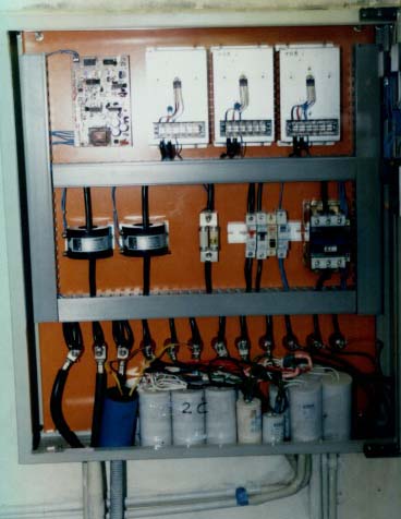
The IGC housing open:
- Top left corner: The Printed Circuit Board.
- Top right: Three heat sinks with a BTA41B triac
in the middle and a varistor over its terminals.
Current rating of these triacs is 40 A, so
theoretically, capacity could be as high as 230 V
* 40 A * 3 triacs = 27600 W, or 27.6 kW. With 24.3 kW of
dump loads connected to them (see commissioning report),
they are loaded up to 88 % of this theoretical capacity.
- Middle, from left to right, there are 2 large
current transformers, "130 A Semiconductor"
fuses to protect the triacs, MCB's to switch off
the capacitors in case of a runaway situation,
and the 65 A, 3-phase main relay.
- Bottom: The connection terminals and capacitors
to provide magnetizing current to the induction
generator.
|
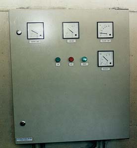
The front panel of the housing. |
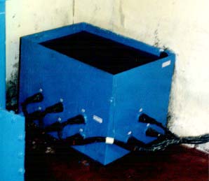
The tank with dump loads. |
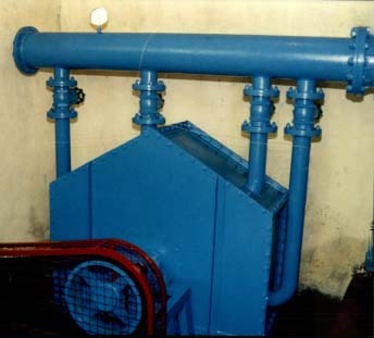
The turbine: A 4-jet pelton turbine. |
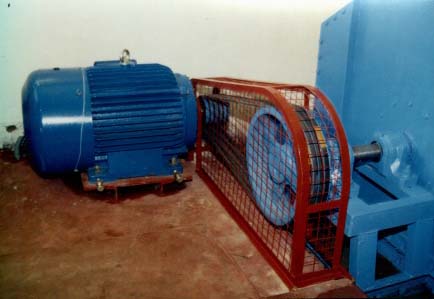
The generator and transmission, with proper protection
against getting your fingers caught by a V-belt |
Commissioning report, summary
| Provider |
Renewable Energy Development Pvt Ltd |
| Location |
Kolonne - Magoda |
| No of Consumers |
140. |
| Date |
28/1/2001. |
| Generator |
3-phase induction motor, 1472 RPM, PF =
0.88 |
| IGC capacity |
22 kW. |
| Dump loads |
His IGC has 3 dump load connections (or
"channels" as mr. Fonseka called them). Each
dump load consists of three 2.7 kW heating elements
connected in parallel. So total dump load capacity is 24.3
kW. |
| Capacitors |
1200 µF in total, in "C - 2C"
arrangement. |
| Generator |
A 3-phase, 22 kW, 1472 RPM induction
motor. Designed for 50 Hz grid frequency, power factor is
0.88 . |
| Measured data: |
| Gross head |
43 m. |
| Net head |
34 m. |
| Generator currents |
For the 3 phases: 53 A, 65 A and 60 A
respectively
(With the turbine running on 3 jets) |
| Generator voltages |
For the 3 phases: 233 V, 230 V and 219 V
respectively |
| Frequency without consumer load |
54 Hz. |
| DC voltages |
0.5 - 1 V DC at generated voltage, 0.5 -
1 V DC at dump load voltages |
Dear Portegijs,
I could not contact you for a
long time. I hope you are keeping well. Recently I moved to a
new house and my email address got changed since the service
provider is unable to provide the service.
I have completed a project for a
Sri Lankan Company. It is a 50 Kw 3 Phase IGC. The photos are
attached herewith. In addition to that I have done one ELC(40KW
3 PHASE) for Philippine company. But haven’t heard from
them yet. I tried to contact them many times too.
...................
Kumar
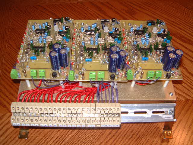 |
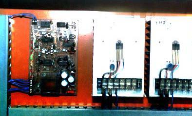
The 3-phase IGC electronics: Just 3
single phase PCB's. Transformers, relay's, fuses or
circuit breakers are not visible so I guess they will be
placed somewhere else in the housing.
|
Below the PCB's, there is one large heat sink with,
for each phase, 3 triacs. In an earlier email, mr Fonseka
wrote that he intended to use BTA40-600B (Package RD91)
triacs. Under optimal cooling conditions, this type can
conduct 40 A and then capacity of this IGC would be:
3 (phases) * 3 (dump loads / phase) * 230 V * 40 A * 0.001
(to convert W to kW) = 82.8 kW
So using it at 50 kW leaves a healthy safety margin. |
 |
Dear Portegijs,
Couple of months ago I fabricated a 3 phase ELC for a Bolivian person. He
installed the ELC and came across a strange situation This is what he mentioned
in his letter:
At first, we calibrated the generator (AVR) for it, we have run the turbine
with out the ELC and we have got 220 V. in each phase and 50 Hz. When we
have connected the ELC suddenly the voltage and frequency have changed. The
voltage got 320V (three hundred twenty V). and the frequency 55 Hz,
immediately again we have calibrated the AVR of the generator.
I don't know why the voltage and the frequency have been changed if at
first its were calibrated. Every time when we turn on the turbine we need
to do this practice. Which is a little uncomfortable for the operators of
turbine, because if the voltage is not regulated immediately the ELC can burn.
I can't find any relationship between the generator voltage and the ELC
since the AVR controls the Voltage.
What could be the reason?
Regards
Kumar
I didn't understand what caused this "strange situation" either. So
I could only write back something about possible disturbance of the generator
AVR by the ELC. This didn't explain all of it, as also frequency was above set
point so this ELC wasn't doing its job either. Mr. Fonseka didn't mention it in
subsequent emails so I guess the problem was solved.
Dear Mr Portegijs,
I couldnt contact you for a long time since I was busy with my new office
work. I have stared my own company in here. Electrical panel design and building
is my main activity and hydropower related activities plays supporting role. I
have been getting little orders and one of my friends is supporting me to carry
out the existing work. The company name is Denon Technologies Ltd. Anyway I have
some thing for you. Can you recall couple of weeks ago you sent me a email
regarding a ELC inquiry. I made a 40Kw elc for them and the photos are attached
herewith.
Drop me a couple of words when you get a chance.
Regards
Kumar
 |
40 kW ELC, heat sink is the biggest part. Probably it
still needs a fan to keep it cool... |
Note: To avoid spam, email addresses are hidden by a script.
If you don't see email links below, enable "javascript" in your browser.
mail to
mail to
Humming bird page