The battery is the single most expensive item in the
investment costs of a firefly system. Also in the running costs,
replacement costs for worn-out batteries form a major part. So
for the economics of the firefly system, it is essential to
choose the most appropriate type of battery and to take proper
care of it. Several types of batteries are worth considering.
- Ordinary car batteries: These are cheap, widely available
in many different sizes, but they will not last long.
They are designed mainly to start a car, so to provide
the very large starting current but only for a few
seconds, so that still they are discharged only a tiny
bit. In a firefly system, the battery must deliver a low
current during a long time and will not be recharged
immediately afterwards.
Once they are discharged to 50 % state of charge, they
have to be recharged again so only 50 % of the total
battery capacity can be used.
- Heavy duty car batteries: These are designed to last
longer under heavy use in a car, truck or bus and
consequently they are more expensive. The plates are
thicker and the separators between plates are made of
glass-wool. Also in a firefly system, they should last
considerably longer.
- Solar batteries: These are designed for use in solar
energy systems. Like with the heavy duty batteries, the
plates are thicker and they have glass-wool separators.
On top of this, the active material is mechanically
stronger and this makes that they can be discharged until
only 20 % state of charge, so 80 % of the total battery
capacity is available. Even when used so heavily, they
still last many more cycles than a car battery. Probably
`lighting' and `semi-traction' batteries have virtually
the same characteristics.
However, they also have disadvantages:
- They are quite expensive.
- They are not widely available yet.
- The size that is commonly used in solar energy
systems is a bit too large for a firefly system.
It is heavy (nearly 30 kg) and such a high
capacity is not really needed. A solar battery of
half this size for half the price would be much
more attractive but these are even more difficult
to get.
- Worn-out car batteries: It could be that batteries that
are too weak to start a car, can still be used in the
firefly system. There are 5 major mechanisms that make a
battery wear out or could destroy it in one go (see annex
C.3: What makes batteries wear out). Batteries that are
not usable for cars because of one of these mechanisms (oxidation
of grid of positive plate), should be still useable for
lighting lamps. Such batteries have retained a large part
of their original capacity to store electricity but due
to the weakened grid, they can not deliver the high
current that is needed to start a car. Luckily this is
the most common mechanism that makes batteries wear out
in a car so a good percentage of all worn-out car
batteries should be usable.
Of course the low price of such batteries makes this
option very attractive, but there are also problems:
- Used car batteries should be tested to see
whether they are useable (it could be that a
battery has become unusable because of one of the
other mechanisms). A test procedure must still be
worked out and operators have to be trained in
performing such tests.
- There should be a way of setting a reasonable
price for a battery that came out as usable from
the tests.
- Even with the above things settled, there is
still a larger risk that a used car battery will
wear out too fast and the owner will be
disappointed.
Therefor is seems best to avoid disappointments and
use new batteries as long as the firefly technology is
still new in the area. In a later phase however, it is
worthwhile to start experimenting with this. It offers
opportunities to reduce investment costs substantially,
which makes it possible for poorer people to join in.
Even when the life span of used car batteries would be so
short that solar batteries seem as cheap in the long run,
it could still be advantageous to choose for old car
batteries because:
- The low investment costs make it affordable to poor
people even if there are no sources of cheap credit.
- Used car batteries will be widely available so that no
development project is needed to get parts from faraway
places.
Then batteries differ with respect of their casing (plastic or
bakelite), the type of connections, whether they have plugs for
topping up with destilled water or are `maintenance-free'. These
things are less relevant so the cheapest design is the best.
Prices of batteries and availablility will vary all over the
world and therefor it is impossible to say which type is the most
advantageous. In choosing a type of battery, mind the following
criteria:
- Costs.
- Availability (also in the long run, when there is no
development project to organise things).
- Life span: This is a difficult thing to estimate. In the
Cambulo project it was estimated that, with good care,
car batteries would last 1.5 year and solar batteries 3
years.
- Effective capacity: This is the part of the total
capacity that can actually be used, so 50 % of total
capacity for car batteries and 80 % of total capacity for
solar batteries. A high effective capacity is
advantageous because it means that a battery needs to be
recharged less often (saves time and money) and/or more
lamps can be connected to it.
- Weight: Of course a low weight is desirable because
batteries need to be carried to the charger regularly.
The weight is more or less proportional to total battery
capacity so only solar batteries can have a high
effective capacity combined with a moderate weight.
Especially the weight should not be forgotten. Generally
people in mountainous areas are used to carry heavy loads for
considerable distances. But this should be no reason for letting
people carry excessively heavy batteries in an attempt to cut
costs. In western countries, regularly handling weights as little
as 25 kg proved to be damaging for health. If batteries are
heavy, it is even more likely that carrying them will be seen as
men's work. So if men move out to work elsewhere or are unwilling
to carry, there is no one to bring them to be recharged.
Preferably also women and older children should be able to carry
batteries.
Many other issues relate to proper battery care. These are
dealt with in other paragraphs and chapters. See also annex D:
More about batteries.
| 5.2 |
Lamps, switches and cables |
The following types of lamps can be used in a firefly system:
- Ordinary 12 V car bulbs: These are by far the cheapest
and also the sockets are quite cheap. The type of 15 W (sometimes
referred to as `21 CP') is the most applicable. This is
the type that is fitted in the indicator lights. Bigger
lamps (like headlights) consume too much electricity and
smaller types (rear lights) give too little light for use
in a normal room. Of course headlight lamps could be used
on occasions when a lot of light is wanted, and smaller
lamps in cases when many lamps have to be powered by one
battery.
A disadvantage of using car bulbs is that they burn a bit
dull. Car bulbs are made for using them at about 14 V (the
voltage when the motor is running and the battery is
being recharged) instead of 12 V. In the firefly system,
the battery is being discharged and the voltage is 12 V
or even less. This makes that the efficiency of car bulbs
(= amount of light produced per amount of electricity
consumed) is quite low.
- Halogen lamps for interior lighting (12 V types). A
halogen lamp in itself is more efficient than an ordinary
filament lamp and on top of this, such halogen lamps are
designed for 12 V and not 14 V. This makes that a 20 W
halogen lamp produces a lot more light than a 15 W car
bulb while it consumes hardly more electricity. There are
two versions:
- A normal bulb.
- A bulb combined with a reflector.
The type with reflector produces a beam that for
instance provides ample light at a working table.
Fitting halogen lamps poses some problems:
- The bulb itself and its leads get quite hot. That
is why special ceramic connectors for halogen
lamps are used, but these are about as expensive
as the bulb itself. However, with some care, 20 W
halogen can also be connected on 2 pieces of a
connector block. The type with reflector does not
become very hot. With the bare bulb, some extra
measures are adviseable to prevent that the
connector and the cable isolation will get too
hot (fire risc!):
- Do not obstruct natural ventilation
around the bulb
- Preferably have the heat-sensitive
connector and cable besides the bulb and
not in the hot air stream above it.
- Use thick, massive cable for the last bit
to the lamp. The copper inside it will
conduct heat away from the bulb.
- The bulb itself should not be touched with bare
fingers (or it should be wiped off with alcohol)
because the substances that make fingerprints,
will noticeably reduce the lifespan of the bulb.
With the type with reflector, the bulb itself
usually can not be touched because there is a
glass plate that covers the reflector and with
these, there is no problem
In Holland, halogen lamps are not too expensive any
more: About ƒ 5 for a bulb type and ƒ 10 for a
reflector type. The smallest size used to be 20 W but
nowadays also bulb types of 10 W and even 5 W can be
found.
- Ordinary fluorescent lamps with a special 12 V ballast.
Compared to car bulbs and halogen lamps, these are very
efficient. In the Philippines, a complete 20 W
fluorescent lamp set was available for about ƒ 13.50
but the life span of the lamp itself proved to be
disappointingly low. Apparently the simple ballast
circuit makes it wear out too fast. Types with a better
ballast should not have this problem, but are much more
expensive.
Such electronic ballasts work with a high frequency and
at least the cheap ballasts can produce noise on a nearby
radio. To prevent this, an `Elco' capacitor of ca. 63µF,
16 V should be connected over the input wires of the lamp.
Make shure that the lamp and the Elco capacitor are
connected with the correct polarity.
- Ordinary fluorescent lamps with 220 / 110 V ballast plus
an inverter to convert the 12 V DC from the battery into
220 / 110 V AC. These lamps themselves are cheap, very
efficient and have a long life span. For powering just
one lamp, the costs of the inverter are too high to make
this an economic solution. But when there are many lamps
that are normally on at the same time, this might be an
attractive option. This could be the case if there is one
large building (e.g a school building that is also used
at night, a church or a community centre). It could also
be the case if there are a number of houses to be powered
from one battery. Cable losses in the 220 / 110 V cable
will be minimal so even houses a few hundred meters away
from the battery could be connected using very thin
cable, as long as this cable is suitable for 220 / 110 V.
See under `inverter plus ordinary 220 / 110 V appliances'
in par. 5.3 for more technical details.
- Special `PL' types of fluorescent lamps with 12 V ballast.
These are extremely efficient and that is why they are
used in solar energy systems. As long as the special 12 V
ballast can not be made locally and cheap, they seem too
expensive yet for a firefly system. Contrary to a solar
system, firefly users are probably poor, do not need that
much light and producing the electricity (= charging the
battery) is cheap.
For choosing the best type of lamp, the following issues
should be considered.
- How much light is needed. Is it for cooking a meal or for
reading.
- Costs. The money saved by buying cheap car bulbs could
easily be offset again when a larger capacity battery is
needed to power these lamps, the battery has to be
recharged more often (charging fees) and wears out faster.
Also the time spent on bringing the battery to be
recharged should be treated as costs.
- Preferences for a certain kind of light.
The electricity consumption per day of a user depends on:
- The number of lamps fitted.
- The rated power of these lamps (in Watts).
- The average number of hours per day that each lamp is on.
Quite likely, richer users will want lamps that provide more
light because they can afford it. Probably they also have bigger
houses with several rooms and will buy more lamps so that there
is a light in each room. If they would use the same kind of lamp
(probably car bulbs) as poorer users, they would have a much
higher electricity consumption so then the charger is not used
equally by all users of one group. This could cause disunity
within this user group once it comes to dividing the costs of the
charger. A way to minimise this problem is, to advise users who
want more light to buy more efficient lamps rather than lamps
with a higher rated power. This will make the electricity
consumption of all users more equal.
For cables, the cheapest type is probably the best. This is
usually `twin cable', the simplest kind of cable for indoor use
as cord for 220 / 110 V appliances. It consists of two insulated
wires melted together and without a coat around both of them. The
wires are stranded so it can stand being bent many times. It is
not a high quality cable that will last many years under harsh
conditions but it is cheap and widely available.
The thickness of cables should be chosen so that the voltage
drop over it will remain below 5 % of the total voltage (= 12 V),
see table 5.1 for some practical guidelines. In annex 0: Formulas
and reference data, an explanation is given on how to calculate
voltage drops in cables.
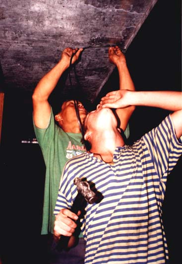 |
Fig. 5.1: Ruud Portegijs helps Leon Bentican wiring
up his house. |
Cables can be fitted on wood with electrical staples or nails
that are partially hit into the wood and then bent over to hold
the cable. When a cable spans a distance outdoors (for connecting
a nearby house to the same battery), it is best to tie a cable so
that it does not hang on a staple or a nail.
For connecting cables, connector blocks can be used but just
twisting the wires together and insulating the joint with
electrical tape is cheaper and it is likely that this will be
done anyway when users want to expand their system using bits and
pieces of cable.
As switches, ordinary 220 / 110 V switches will do, probably
are the cheapest and are easily fitted on walls.
Using the cheapest materials for wiring up a house inevitably
will lead to more technical failures and a lower life span.
Besides this, in principle there are safety issues at stake. With
the firefly home system, those safety issues do not depend
strongly on the quality of materials. The voltage itself is
harmless to touch and the only risk is a cable catching fire due
to a short circuit. The protection against this is formed by the
battery fuse and consequently this fuse is essential (see par. 5.5).
Using a sturdier cable would of course reduce the risc that a
short circuit occurs, but in an environment with choppers,
spades, axes and children around, even a cable with a steel coat
would not be totally safe.
Table 5.1:
Selection of cable type.
Cable between battery connection and
indicator:
- Always 2.5 mm² (or no. 14 in American Wire
Classification)
- maximum length = 2 m.
|
| Cable cross section: |
Cables between indicator and lamps:
Maximum cable length (in m) for total power is: |
| 10 W |
20 W |
30 W |
40 W |
60 W |
80 W |
100 W |
| 0.75 mm² |
15 |
7.7 |
5.1 |
- |
- |
- |
- |
| 1.31 mm² (no 16) |
27 |
14 |
9.0 |
6.7 |
4.5 |
- |
- |
| 1.5 mm² |
31 |
15 |
10 |
7.7 |
5.1 |
- |
- |
| 2.08 mm² (no 14) |
43 |
21 |
14 |
11 |
7.1 |
5.3 |
4.2 |
| 2.5 mm² |
51 |
26 |
17 |
13 |
8.5 |
6.4 |
5.1 |
| 3.31 mm² (no 12) |
68 |
34 |
23 |
17 |
11 |
8.5 |
6.8 |
| 5.3 |
Minor uses for electricity |
Although lighting will be the main use for practically all
users, there are some other uses that are inexpensive and
worthwhile:
- Connecting 6 or 9 V appliances to the firefly battery
instead of using dry cell batteries. In this way, the
money for dry cells for radio's, cassette players and
similar appliances that are used within the home, can be
saved.
- Recharging rechargeable NiCd batteries or small,
maintenance-free lead-acid batteries. Such batteries
could then replace dry cell batteries in torches and
other outdoor appliances. The need for torches is much
higher in an environment without street lights, outdoor
lights and cars or bicycles with their own lamps and a
good torch is more or less a safety device when one has
to go out along a slippery path in the dark.
Consequently, the consumption of dry cell batteries for
torches is quite high, once people can afford these.
. NiCd batteries of the size for torches are quite
expensive but nowadays small maintenance-free lead-acid
batteries from emergency lamps are available reasonably
cheap. These do not fit in a torch itself, but could be
tied onto it. The lead-acid battery can be connected to a
wooden stick with connections on both ends that acts as a
`dummy-battery' and fits inside the torch.
- Appliances other than lamps that can be powered directly
from 12 V, for instance:
- Appliances designed for use in cars: Small 12 V
electrical fan, car radio/cassette player etc.
- Appliances designed for use in a solar energy
system: Solar refrigerator for vaccine cooling.
- Other appliances that can use 12 V: Two way radio
systems, portable computers with an adapter for
12 V.
- Using an inverter, a device that turns 12 V DC (decent
current) into 220 / 110 V AC (alternating current). Most
normal 220 / 110 V appliances can be powered by such an
inverter, as long as the power they need is within the
capacity of both the inverter and the battery.
The most likely appliance this will be used for, is for
powering a video recorder + television set and showing
video's for an entrance fee. From the economic point of
view, this could be quite attractive (in fact it probably
is the only productive end-use that fits well within the
firefly system). What kind of movies will be shown and
whether this is a desirable development, is another
question. In Ifugao prov. in the Philippines, children
started stealing money for going to the movies once such
video cinema's came in.
Another possible use is to power a number of ordinary 220
/ 110 V fluorescent lamps in one large building, or in a
number of houses, see par. 5.2.
The technical aspects of these options will be discussed below.
To power 6 and 9 V appliances from the main battery, the
voltage must be reduced by a stabilised voltage supply. This is a
cheap electronic component that produces a constant output
voltage from a varying, higher input voltage. To prevent
oscillation problems (so: radio interference), capacitors are
connected to the input and output of the device. See fig. 5.2a
for the electronic circuit.
The device, capacitors and connection cables can be fitted
into 3 units of a small connector block so no soldering is needed
for that. At the end of the output cable there should be a
cylindrical plug that fits in the appliance (if the appliance has
no socket for this, fit a socket to the connections for the
batteries inside). It is adviseable to fit a socket + plug at the
input side as well so that the stabilised voltage supply can be
disconnected from the battery in case it is not needed. These
sockets and plugs have to be soldered on. Since current is so
low, cables can be as thin as is practicable, say 0.4 mm² (nr.
20 in American classification). Normally, the power consumed by
the appliance is so low that the stabilised voltage supply device
needs no cooling. Only when it gets very hot (too hot to touch)
it should be mounted on a piece of aluminum sheet that acts as a
cooler.
For fire protection, either the battery fuse should blow in
case of a short circuit, or a separate fuse (of ca. 1 A) should
be fitted in the input side, see annex 0: Formulas and reference
data. If there is no separate fuse, the total length of thin
cable (input and output) should be no more than 4 m (with 16 A
battery fuse and thin cable of 0.4 mm²). Then it is best to have
the device itself near the main cable.
For 4.5 and 3 V, a slightly different circuit is needed
because a `7804.5' and 7803' stabilised voltage supply does not
exist, see fig. 5.2b. In this case, 4 units of a connection block
are needed to mount all components, 3 for the connections of the
LM 317 and a separate one for the `-' wire.
NiCd batteries should be recharged with a constant current.
This can be done simply by fitting a series resistor that limits
the current to the desired value, see fig. 5.2c. After the stated
charging time, they should be fully charged. To economise on the
electricity consumption from the main battery, it is best to
recharge as many batteries in series as possible. To make this
into a handy device, a battery holder can be made with a
different slots for each size and number of batteries that are to
be recharged in one go. Then for each slot, the right resistor
can be fitted.
A problem with the circuit given in fig. 5.2c is that for each
current and each number of batteries recharged in one go, another
resistor value is needed. An alternative for this is to use a
`Constant current device', see fig. 5.2d. Then with the same
device, 1 up to 6 batteries that need the same charging current,
can be recharged. The LED will burn less bright if more batteries
are recharged, but this does not influence the charging current
itself.
 |
Fig. 5.2a: Stabilised voltage supply for 6 V output.
For 9 V output, use device `7809' instead of `7806'.
|
 |
Fig. 5.2b: Stabilised voltage supply for 4.5 V or 3 V.
|
 |
Fig. 5.2c: Charging NiCd batteries with a series
resistor to achieve the right current.
|
 |
Fig. 5.2d: Constant current device for recharging 1
up to 6 NiCd batteries in one go.
|
 |
| Fig. 5.2e: Circuit for recharging small, 6 V,
maintenance-free lead-acid batteries from the main
battery. The LM 317 must be mounted on a piece of
aluminum for cooling. The part of the circuit with
transistor and LED's can be omitted, it only serves to
show whether the charger is functioning and whether the
battery is charged already. |
Like the main battery, maintenance-free lead-acid batteries
need to be recharged with the right voltage and current (see par.
4.9.5.1). Instructions for this are written on the battery
itself, see with `cyclic use'. On a YUASA NP 4-6 battery (6 V, 4
Ah capacity) it said: `voltage regulation: 7.2 - 7.5 V, initial
current: 1 A max.'.
A fine-tuned version of the stabilised voltage supply of fig.
5.2b, could provide the desired voltage while a series resistor
in the input wire could limit the current to 1 A maximally. See
fig. 5.2e for the electronic circuit. To make things really
perfect, a circuit with two LED's can be added that will indicate
whether the device is charging (red LED) or that the battery is
practically charged (green LED, current has dropped below 0.2 A).
The voltage is adjusted by the 2.5 kOhm trimmer (range: 1.25 -
7.9 V). The current limitation is set to ca. 1 A by the series
resistor in the input wire, in this case 4.7 Ohm. For another
current limitation value, choose another resistor: First
calculate the voltage over the resistor: 12 - 6 (maintenance-free
battery) - 1 (LM 317) = 5 V. Then calculate what resistance gives
the desired current with Ohm's law, see annex 0: Formulas and
reference data.
Of course appliances that can be powered directly from 12 V,
can be connected directly to the battery. However, one has to
check how much electricity they consume. For instance a small 12
V electric fan of only 12 W but used 12 hours a day, would still
drain a small car battery in only 2 days and users might be
disappointed by this. But if a notebook computer would consume as
much power, being able to work 24 hours on one small car battery
might be seen as quite good.
Solar refrigerators consume so much electricity that carrying
batteries to the charger is not feasible. Instead, the solar
refrigerator should be placed very close to the charger (or the
charger to the solar refrigerator) so that the batteries can be
connected without moving them. Then in principle, no batteries
would be needed and the refrigerator could be connected directly
to the charger. But then the charger would run idle once the
temperature inside the fridge has reached the desired value and
the thermostat switches off the pump. Also the vaccines would be
lost in about a day once the charger breaks down. Therefor it
seems best to have a buffer of 1 or 2 large solar batteries. The
costs of these are low anyway compared to the costs of the solar
fridge itself. During the night, the charger can be used to
recharge these batteries while at daytime, these batteries can be
disconnected and the batteries of other users recharged. Of
course the electricity consumption of the fridge + losses in its
batteries + electricity need for recharging batteries of other
users, should not surpass the maximum electricity production of
the charger running day and night.
To charge batteries properly, the cable between the
switchboard and the battery should have a specified, low
resistance (see par. 4.9.6). which means that a 2.5 mm² cable
should be only 2 m long. So either the cable between the charger
and switchboard must be made longer so that the switchboard can
be placed close to these batteries, or the batteries have to be
placed close to the switchboard and charger. In both cases, still
the voltage drop over the long cable should be checked (see annex
0).
Generally, solar fridges are too expensive and have too small
a capacity (in liters of useful storage room) to be feasible for
e.g. storing food or softdrinks, or producing ice for human
consumption. Only for the richest people (development workers
themselves) or tourist lodged, this might be an option.
Using an inverter with normal 220 / 110 V appliances might
seem an attractive option since the normal 220 / 110 V appliances
are relatively cheap. But there are some drawbacks:
- Many 220 / 110 V appliances just consume too much power.
Examples of these are: Refrigerators, ironing devices,
electric heaters, powerful electric motors and large fans
running many hours. For these, several large batteries
might be needed for one house, still they might need
recharging after only a few days and also the inverter
needs to have a very high capacity.
Even with all 220 / 110 V appliances switched off, the
inverter will still consume a little bit of power and
therefor it might not be feasible to have the inverter
switched on 24 hours a day.
- Often special 12 V appliances are more efficient than the
usual 220 /110 V appliances. Fluorescent lamps are an
exeption to this.
- The inverter produces a rather crude form of Alternating
Current and some electrical devices might not work
properly on such an input voltage (electrical clocks,
some computer equipment).
- Safety. The 12 V from the firefly system itself is safe
from the point of touching live wires. People might get
used to this and connect the 220 / 110 V cables in the
same cheap but unsafe way.
This option might be attractive for powering a number of
cheap, efficient 220 / 110 V fluorescent lamps, see par. 5.2.
The current in a 220 V cable will be only 5.5 % of that of a
12 V cable transmitting the same amount of power (11 % in case of
a 110 V cable). Therefor the thinnest cable that is suitable for
220 / 110 V can be used for the 220 / 110 V cables and still
cable losses within a building will be negligible. Even houses a
few hundred meters away could be connected up using such thin
cable without significant cable losses.
index page
next