This article was published in: Energy for Sustainable Development, Volume II No. 2, July 1995


FIREFLY MICRO HYDRO SYSTEM

Jan Portegijs

The firefly system is a very small Micro Hydro system that is primarily intended for lighting purposes in isolated communities without grid connection. For storing electricity, 12 Volt car batteries can be used but `solar' batteries will last longer. Batteries also serve as a means of transporting electricity from the charger site to the houses since cables for 12 V would become too expensive.

Twelve volt lamps and other 12 V appliances can be powered directly from the battery. Other appliances that work at 3, 4.5, 6 or 9 V and are normally powered by dry cell batteries, can also be connected by fitting a simple electronic part in between. With an inverter, ordinary 220 V appliances can be used as long as their power demand is not too high.

The first prototype firefly system was designed, built, tested and introduced in a pilot community by the author in 1992 while working at the Philippine Rural Reconstruction Movement (an NGO) in Ifugao prov., Philippines. Back in Holland, the design was developed further and documented in a building manual. Meanwhile, the Ifugao pilot project faced serious technical and organisational problems. End of 1993, a successor arrived, things started to roll again and 3 other PRRM branches now have plans for introducing the firefly in their work area. Two `Affiliated Non-conventional Energy Centers' (`ANEC's', projects under the Dept. Of Energy, affiliated to universities) have chosen the firefly design for their Micro Hydro activities. These two ANEC's have given trainings to staff of 17 other ANEC's and through this Philippine-wide network, the firefly could be introduced on a wider scale.
Fig. 1. The firefly charger seen from below: Not a big thing.


Fig. 2: Cross-section through runner and nozzle. To get a paper copy at the right scale: Print drawing at 150 DPI.
Notes:
The runner is made of 61 x 19 x 1.25 mm blades soldered with brass into 3 mm thick side disks. To make side disks, use copies of this drawing, glue them on material and mark relevant points with a centre punch. The slots in side disks can be cut using jigsaw sawblades for metal fixed in a makeshift sawframe. To be able to cut slots with such a small radius, the sawblades must be reduced in width by grinded off at the rear end, opposite the teeth, see lower inset. The 20 mm central hole in the free side disk is needed to fit the thick washer (see fig. 4), the alternator side disk has a 6 mm central hole.
The nozzle is made from 2 mm steel, 53 x 83 mm for the runner side and 53 x 138 mm for the bent side. For alternator side and free side, use copies of the drawing. The rounded-off edge of runner side (see top inset) is not essential but without it, flow and electrical output will be ca. 10 % lower than given in fig. 3. Weld nozzle parts together in such a way that inside width (the direction perpendicular to the drawing plane) is 51 mm.
When welding on the frame (see fig. 1 for how this could look like), make sure that welding current will never pass through the alternator bearings.

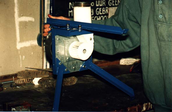
Fig. 3: The seal and the way the runner is fixed on the alternator shaft.
Notes
For simplicity, not all visible lines are drawn. Parts hatched to the left come with the alternator, parts hatched to the right have to be made, use 1 or 1.25 mm steel, preferably galvanised. The seal has clearances of only some 0.5 mm between moving and stationary parts and this will protect the alternator against water coming from the turbine (covers around the alternator should protect it against rain and tailwater splashing back from rocks etc.). The runner can be fixed by one M6 bolt, but make sure it pulls the runner against the rim of the alternator pulley, not against the end of the shaft itself. Under the bolt head, there should be a 6 mm thick washer (outer diameter: 20 mm, hole: 6 mm) to prevent the alternator side disk from bending too much.

Notes to html version:
In this drawing, the anti-splashing disk is not included, see with Leakage around seal for pulley in one piece
To get a paper copy at the right scale: Print drawing at 150 DPI.


The firefly system consists of 2 major components: The firefly charger and the home systems. The charger basically is a second hand car alternator with a `crossflow' runner mounted directly on the shaft, see figs. 1, 2 and 3 (see HARVEY, 1993 for a description on crossflow turbines). It might seem this charger is the major component as it is the part that generates electricity. However, economically speaking it is not: batteries and other materials for the 10 home systems that are typically served by one charger, are about 5 times as expensive as a locally built charger. Also in running costs, the batteries are the critical element so proper battery care is vital. This means among others that batteries should not be discharged too deep and should never be left in discharged condition for long. Therefore the charger should always be ready for charging batteries, which it will when it is built properly, the operator is around and knows his/her job and there is water to power it.

The firefly charger is quite flexible with respect to the head (= water pressure in m) it can operate at, see the characteristics in fig. 4. At high head, flow and output power can be reduced by inserting a blocking timber in the nozzle. Over the whole head range, the charger can operate at its optimum speed because field current can be regulated, see fig. 5 for the electrical circuit of both charger and home system.

The home system includes the battery, lamps, switches and the wiring to make these work. It also includes the firefly charge indicator, a small piece of electronics that shows how far a battery has been discharged by means of 10 LED's. It is located near the switch of a lamp that is often used and is activated when this lamp is turned on. The fact that it lights up will draw the attention of users, even more so because before showing its final reading, the LED's indicating a lower voltage light up briefly. For more accurate readings, there is a push-button switch to activate the charge indicator without any lamps being switched on. So prime responsibility for not discharging batteries too deep, lies with the users who own them. As a back-up, the operator of the charger should check whether batteries were discharged too deep before charging them.

Major advantages of the firefly system are:

  • It is Cheap: In the Philippines, a complete charger was estimated to cost $ 150 while the materials for a home system were about $ 75 (1992 prices, labour done by users not included). So with 10 users per charger, investment costs are only $ 90 per user, or about 1/10-th of the investment costs of a solar home system at the time.
  • Introducing it is simple: Compared to 220 V A.C. systems, the firefly system needs only few users to start with and no local electricity grid. Training needs are less because 12 V is safe to touch and operators can learn by trial and error. Finding a suitable site is easier and digging a canal is less work since it requires only a small flow and a low head. Also the firefly charger can be demonstrated by using a motor pump or a makeshift water source before investing in a permanent canal, batteries etc.
  • Local production is possible: Car repair workshops can produce the mechanical parts of the charger while electronics repair workshops can build switchboards and charge indicators.

  • Fig. 4: Charger characteristics.
    Notes
    Above 7 m head, electrical power would become too high for charging only one battery. Then output power can be limited by inserting a blocking timber in the nozzle that blocks part of nozzle width. Above 15 m head, a blocking timber of at least half nozzle width is needed to keep forces on runner blades within limits.

    These characteristics are based on an assumed overall efficiency of 0.30 . For a neatly built charger fitted with a good alternator, overall efficiencies of up to 0.40 are achieveable. If electrical power is disappointingly low, check:

    • Electrical system (see fig. 5). As long as the battery is relatively empty, the voltage regulator should provide full field current. If not, check its adjustment and make sure voltage drop to battery poles is low.
    • Measure field current: If this remains below 2.5 A even with all field current lamps on, check alternator brushes. Fit a better seal if brushes have become wet. Check whether actual speed is close to optimal speed for turbine (= about 60 % of free running speed). Reduce or increase the number of field current lamps being switched on until charging current is highest.
    • Pipe losses (measure net head at nozzle inlet). To reduce pipe losses, fit a larger diameter pipe or a wider blocking timber.
    • If runner and nozzle are built rather crudely, check how much water is leaking past the runner. Fit the nozzle closer to the runner to reduce this.
    Fig. 5: Electrical circuit.
    Note
    Experiences in the Philippines indicate that many technical problems had to do with the electrical system, some comments:
    • Many alternator types exist and most of them will have different codes for connections and a more complicated circuit. Check out connections and circumvent a built-in regulator, any extra diodes etc.
    • Both the voltage regulator and the charge indicator should sense battery voltage accurately. Therefore cables between these and the battery should be short (2 m) and thick (2.5 mm˛).
    • Charge batteries until voltage is above 14.5 V and current has dropped below 4 A.
    • Calibrate the 500 Ohm trimmer of the charge indicator until treshold voltage between LED 5 and 6 is at 12.08 V, with no current going through the current shunt.
    • Car batteries need recharging when the first yellow LED (on O5) lights up. Solar batteries can be discharged until the first red LED (O2) comes on.
    The firefly system is not the ideal solution for all situations. Heavy batteries have to be carried to the charger site and back every 1 - 2 weeks and running costs (charging fees, replacement costs for worn-out batteries) are relatively high while power output is too low to allow fridges, ironers and most electrical motor-driven appliances. However, it is an interesting option when the following conditions are met:
    • There is a need for better light than a hurricane lamp or kerosene bottle with wick can provide.
    • Potential users can afford the costs of the firefly system.
    • There is no electricity grid yet and it is not likely to come in the near future.
    • Suitable water sources can be found: With a minimum flow of some 10 l/s throughout the year and in terrain that is so hilly that a drop of 5 m can be achieved after digging a canal of a few hundred meters. Having water all year round is essential: Plenty of water during 9 months of the year is no good if batteries would be stored in discharged condition during the other months and then get badly damaged.
    • Preferably, local people should have experience in building weirs and small irrigation canals.
    • There are car repair workshops and electronics repair workshops in a nearby town that could become involved in local production. For this to become feasible, a certain market is needed, so there should be many potential users and enough suitable sites.

    A first step towards introduction of the firefly would be to build, install and operate a charger as a demonstration project. The draft building manual (PORTEGIJS, 1995) is meant as a guide for this. It requires no more technical background than physics at high school level.

    Lighting usually is not a `productive use': A better quality of light at night does not mean a user will generate extra income with this. Still it has its impact on development issues since proper light could facilitate education, health care, organisation building etc. In the Ifugao pilot community, people did appreciate electrical light, see fig. 6. It adds to the quality of life (see LOUINEAU, 1993). When this could lead to people staying in their community rather than migrating to big cities, it would help alleviating the social and environmental problems there. One could think of many other uses for the firefly that are productive. But generally these will have a limited number of users while a high number of potential users is needed to make local production feasible.

    Other organisations active in Micro Hydro (e.g. ITDG, see HARVEY et al, 1993) work mainly on much more powerful systems, either to produce 220/110 V AC electricity or to drive certain machines directly. Probably this is because in their eyes, productive end uses are essential to make an M.H. scheme economically feasible and those end uses need that much power. Such systems are more expensive, require better trained operators, more users to start with, all investments have to be made before a working system can be demonstrated and their feasibility depends heavily on whether those end-uses are economically feasible. Consequently they are much more difficult to introduce, especially in areas where M.H. is still unknown. Apart of being a useful concept in itself, it is hoped that the firefly will serve as a step towards these more sophisticated systems.


      Fig. 6: A 20 W car bulb provides enough light for a
      native Ifugao house.
    References
    • HARVEY, A. (with A. Brown, P. Hettiarachi and A. Inversin); 1993: Micro-Hydro design manual, a guide to small-scale water power schemes, London, I.T. Publications.
    • LOUINEAU, J.; 1993: Efficient and cost-effective rural lighting systems, in: Appr. Techn. vol. 20 no. 3 page 30 - 32.
    • PORTEGIJS, J.P.J., 1995: The Firefly Micro Hydro system (draft version, Sept. 1995), copies are available with the author.

    index page